

Nanjing Swan simulation software has perfected some classical cycles of SIEMENS 802DM and SIEMENS 810D/840D M :
CYCLE71——face milling ;
LONGHOLE——long hole ;
POCKET4——circular pocket ;
POCKET3——square pocket ;
SLOT1——milling a slot ;
SLOT2——milling a circumferential slot ;
Cycle examples :
CYCKE71 (_RTP, _RFP, _SDIS, _DP, _PA, _PO, _LENG, _WID, _STA, _MID, _MIDA, _FDP, _FALD, _FFP1, _VARI, _FDP1)
_RTP
| real | Retraction plane (absolute) |
_RFP |
real | Reference plane (absolute) |
_SDIS |
real | Safety clearance (enter without sign) |
_DP |
real | Final drilling depth (absolute) |
_PA |
real | Starting point (absolute), 1st axis of the plane |
_PO |
real | Starting point (absolute), 2nd axis of the plane |
_LENG |
real | Rectangle length along the 1st axis, incremental. The corner from which the dimension starts results from the sign. |
_WID |
real | Rectangle length along the 2nd axis, incremental. The corner from which the dimension starts results from the sign. |
_STA |
real | Angle between the longitudinal axis of the rectangle and the 1st axis of the plane (abscissa, enter without sign); Range of values: 0° ≤ _STA < 180° |
_MID |
real | Maximum infeed depth (enter without sign) |
_MIDA |
real | Maximum infeed width during solid machining in the plane as a value (enter without sign) |
_FALD |
real | Finishing dimension in the depth (incremental, enter without sign) |
_FFP1 |
real | Feedrate for surface machining |
_VARI |
integer | Machining type (enter without sign) UNITS DIGIT: Values:1 Roughing .2 Finishing TENS DIGIT: Values: 1. Parallel to the 1st axis of the plane, unidirectional 2 Parallel to the 2nd axis of the plane, unidirectional 3 Parallel to the 1st axis of the plane, changing direction 4 Parallel to the 2nd axis of the plane, changing direction |
_FDP1 |
real | Overrun travel in the direction of the plane infeed (incremental, enter without sign) |
You can mill a optional rectangular plane by using CYCLE71. The cycle distinguishes roughing and finish machining. The cycle machines without radius compensation of milling cutter. Deepness machining is executed when dry run

Fig.1-1
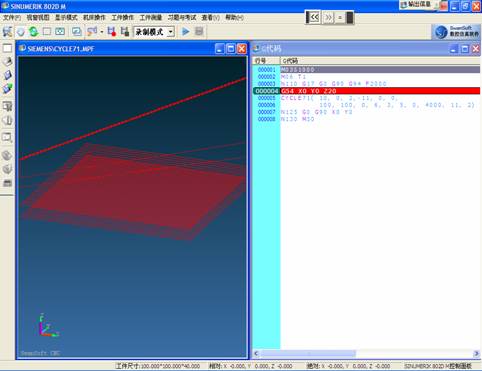
Fig.1-2
Notation : Swan published a accessory tool ( SGD ) on a near day——visualized NC code debugging tool (SGD)
SWANSC G-code debug tool (for short SGD) is a simple and effective built-in tool which can call simulation NC code intuitionisticly, simplely and rapidly. SGD help you call G code rapidly and correctly and check format of each command intuitionisticly. With SGD , you can even check every G code and check every corresponding locus in the condition of a visualized three-dimensional graphics. SGD support kernel code of many NC systems such as FANUC 、 SIEMENS 、 HUAZHONG NC 、 MITSUBISHI.
M03S1000
M06 T1D1
N110 G17 G0 G90 G94 F2000
G54 X0 Y0 Z20
CYCLE71( 10, 0, 2,-11, 0, 0,
100, 100, 0, 6, 3, 5, 0, 4000, 11, 2)
N125 G0 G90 X0 Y0
N130 M30
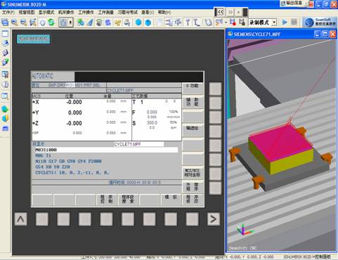
Fig.1-3
POCKET3 (_RTP, _RFP, _SDIS, _DP, _LENG, _WID, _CRAD, __PA, _PO, _STA, _MID, _FAL, _FALD, _FFP1, _FFD, _CDIR, _VARI, _MIDA, _AP1, _AP2, _AD, _RAD1, _DP1)
该循环可以(yǐ)用于粗加工和精加工(gōng)。 在精(jīng)加工(gōng)时要求一个端面铣刀。
深(shēn)度方向进(jìn)刀始终从凹槽中心点开始,或者在那儿垂直进(jìn)行;因此在此位置可以(yǐ)先预钻削孔(kǒng)。
| _RTP | real | Retraction plane (absolute) |
| _RFP | real | Reference plane (absolute) |
| _SDIS | real | Safety clearance (enter without sign) |
| _DP | real | Pocket depth (absolute) |
| _LENG | real | Pocket length, for dimensioning from the corner with sign |
| _WID | real | Pocket width, for dimensioning from the corner with sign |
| _CRAD | real | Pocket corner radius (enter without sign) |
| _PA | real | Reference point for the pocket (absolute), 1st axis of the plane |
| _PO | real | Reference point for the pocket (absolute), 2nd axis of the plane |
| _STA | real | Angle between the pocket longitudinal axis and the first axis of the plane (enter without sign); Value range: 0° ≤ _STA < 180° |
| _MID | real | Maximum infeed depth (enter without sign) |
| _FAL | real | Finishing allowance at the pocket edge (enter without sign) |
| _FALD | real | Finishing allowance at the base (enter without sign) |
| _FFP1 | real | Feedrate for surface machining |
| _FFD | real | Feedrate for depth infeed |
| _CDIR | integer | Milling direction: (enter without sign) Values: 0 Synchronous milling (according to the spindle direction) 1 .Conventional milling 2 .With G2 (independent of spindle direction) 3 .With G3 |
| _VARI | integer | Machining type: UNITS DIGIT Values: 1 Roughing 2 Finishing TENS DIGIT: Values: 0 Perpendicular to the pocket center with G0 1 Perpendicular to the pocket center with G1 2 Along a helix 3 Perpediculation along a pocket longitudinal axis |
| _MIDA | real | Maximum infeed width as a value in solid machining in the plane |
| _AP1 | real | Blank dimension of pocket length |
| _AP2 | real | Blank dimension of pocket width |
| _AD | real | Blank pocket depth dimension from reference plane |
| _RAD1 | real | Radius of the helical path on insertion (relative to the tool center point path) or maximum insertion angle for reciprocating motion |
| _DP1 | real | Insertion depth per 360° revolution on insertion along helical path |
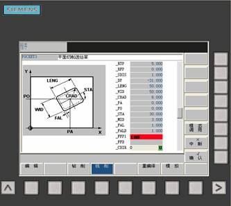
Fig. 2-1

Fig.2-2
M3S800
M06T01D01
G54G0X0Y0Z50
POCKET3 (5, 0, 1, -31, 50,
50, 6, 0, 0, 30, 3, 0.5,
0.5, 100, 100, 2, 11, 3)
M5
M30

图2-3
SLOT2 (RTP, RFP, SDIS, DP, DPR, NUM, AFSL, WID, CPA, CPO, RAD, STA1, INDA,
FFD, FFP1, MID, CDIR, FAL, VARI, MIDF, FFP2, SSF, _FFCP)
Cycle SLOT2 is a combined roughing - finish machining cycle. This cycle can machine ring slot, and these slots lie on an arc.
| _RTP | real | Retraction plane (absolute) |
| _RFP | real | Reference plane (absolute) |
| _SDIS | real | Safety clearance (enter without sign) Safety clearance (enter without sign) |
| _DP | real | Slot depth (absolute) |
| _DPR | real | Slot depth relative to the reference plane (enter without sign) |
| _NUM | integer | Number of slots |
| _AFSL | real | Angle for the slot length (enter without sign) |
| _WID | real | Circumferential slot width (enter without sign) |
| _CPA | real | Center point of circle of holes (absolute), 1st axis of the plane |
| _CPO | real | Center point of circle of holes (absolute), 2nd axis of the plane |
| _RAD | real | Radius of the circle (enter without sign) |
| _STA1 | real | Starting angle |
| _INDA | real | Incrementing angle |
| _FFD | real | Feedrate for depth infeed |
| _FFP1 | real | Feedrate for surface machining |
| _MID | real | Maximum infeed depth for one infeed (enter without sign) |
| _CDIR | integer | Mill direction for machining the circumferential slot Values: 2 (for G2) 3 (for G3) |
| _FAL | real | Finishing allowance at the slot edge (enter without sign) |
| _VARI | integer | Machining type Values: 0 = complete machining 1 = roughing 2 = finishing |
| _MIDF | real | Maximum infeed depth for finishing |
| _FFP2 | real | Feedrate for finishing |
| _SSF | real | Speed when finishing |
| _FFCP | real | Interfix feed, circular orbit, unit:mm/m |
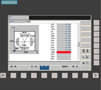
Fig3-1

Fig.3-2
T01D01
G54G0X0Y0Z20
SLOT2 (10, 0, 5, -10, 10,
4, 40, 15, 0, 0, 25, 60,
0, 100, 100, 3, 3, 0.5, 2,
3)
M5
M30
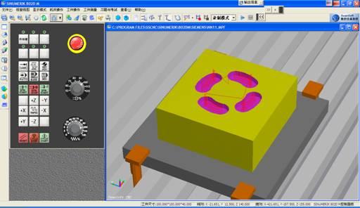
Fig.3-3